Projector throw distance guide and planning tool
Use image width and a projector's throw-ratio range to estimate a planning distance, then verify the actual model, lens and room.
A conservative explanation of throw ratio, image width, zoom ranges and the checks that must happen before a projector is mounted.

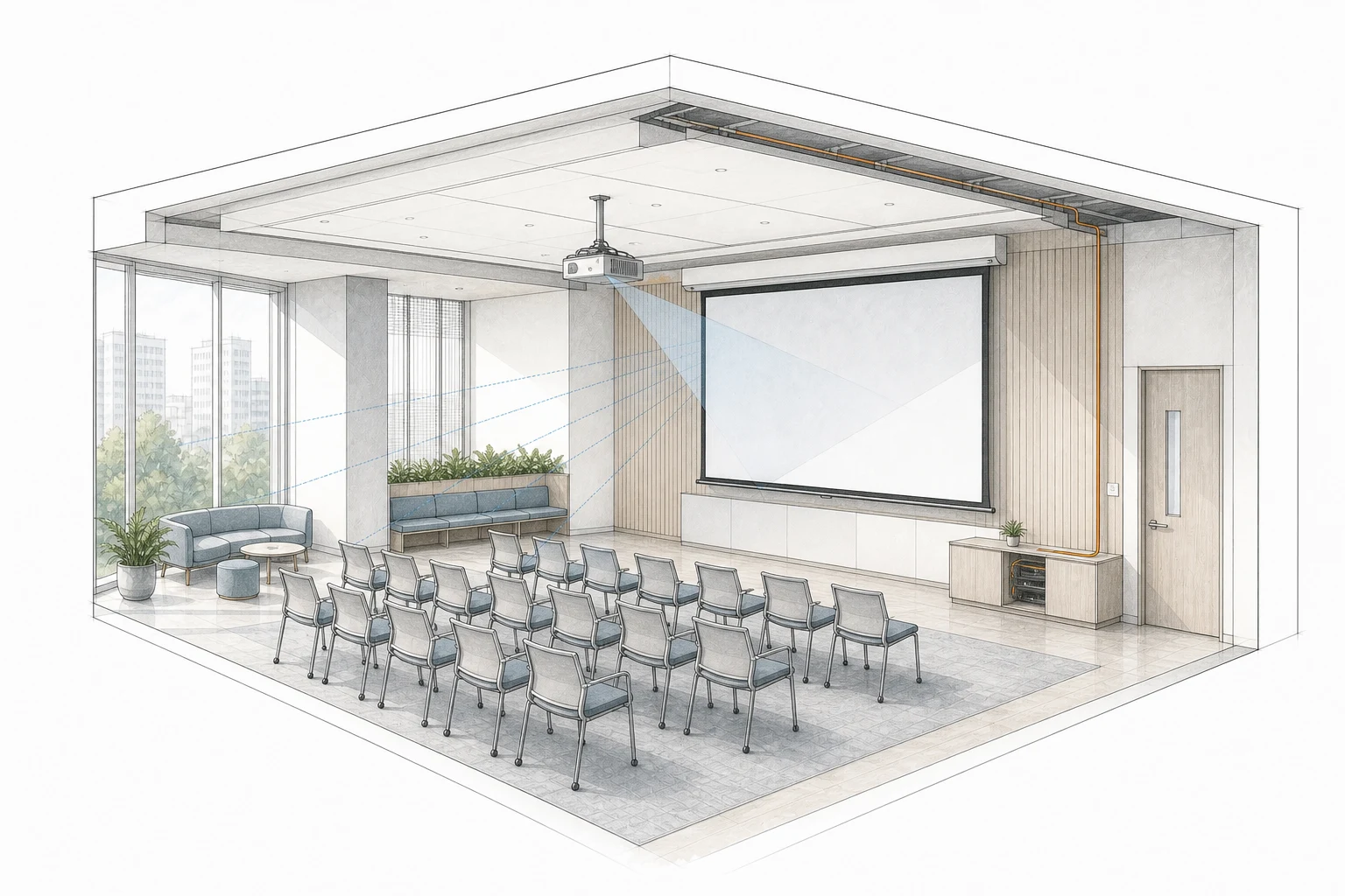
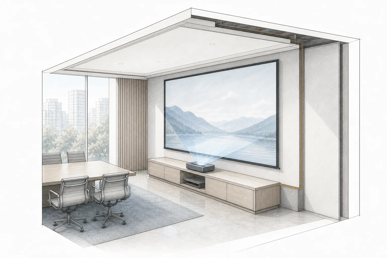
Select a numbered marker to inspect the room detail.
Throw distance is the distance from the projector lens to the projection surface. It is estimated from the image width and the projector's throw ratio. The result below is a planning estimate only: the selected model/lens, lens shift or offset, mounting hardware, screen geometry and room must be checked before installation.
The planning formula
Distance = image width × throw ratio. Use the visible image width in metres and the throw ratio as a number (for example, 1.5 for 1.5:1). If a projector lists a range, calculate both ends. A range can reflect zoom or different lens conditions; it is not permission to place the projector anywhere within the room without verification.
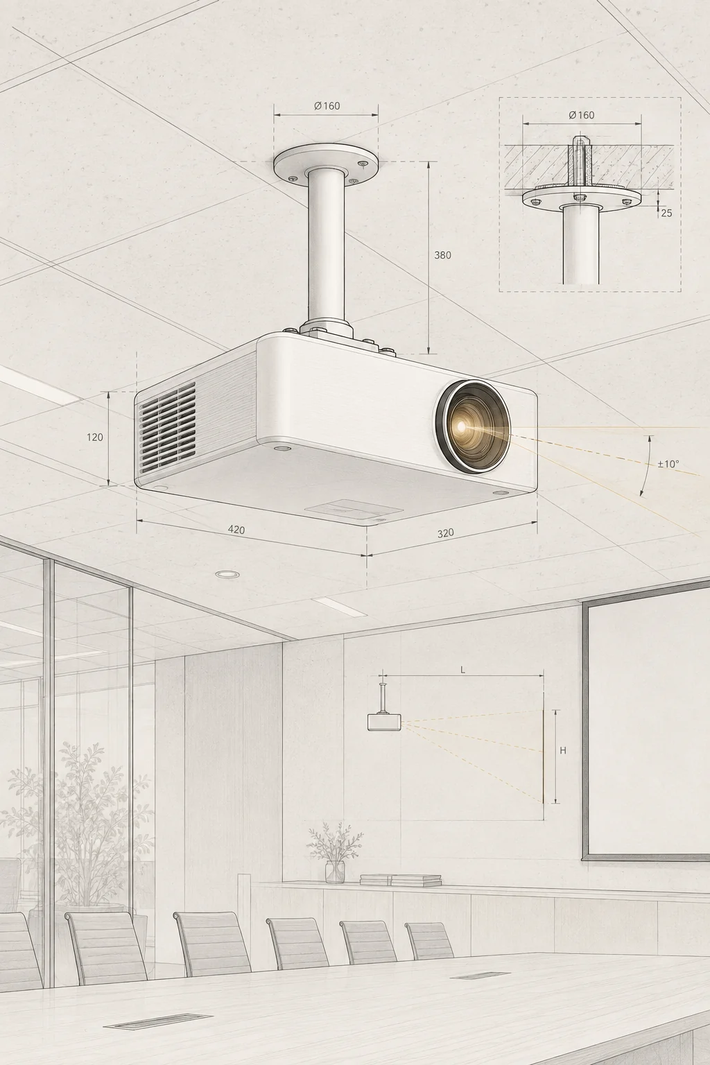
Throw-ratio geometry
The lens-to-screen planning distance is image width multiplied by the selected throw ratio, with mounting depth and service access checked separately.
Throw-distance planning estimate
Enter visible image width and a throw-ratio range. Results are estimates in metres and must be checked against the exact model/lens and room.
Allowed ranges: image width 0.2–30 m; throw ratios 0.1–20:1. Use the exact model/lens documentation before mounting.
Measure the image width first
Throw ratio uses image width, not diagonal size. For a 16:9 screen, convert the intended diagonal into width or use the manufacturer's visible image dimensions. Record whether the number refers to the image area or the outer frame; the formula needs the image area.
Why the estimate can be wrong
- The published ratio may be for a particular lens, zoom position or projection mode.
- Lens position, chassis depth and mounting hardware change the physical back-of-projector location.
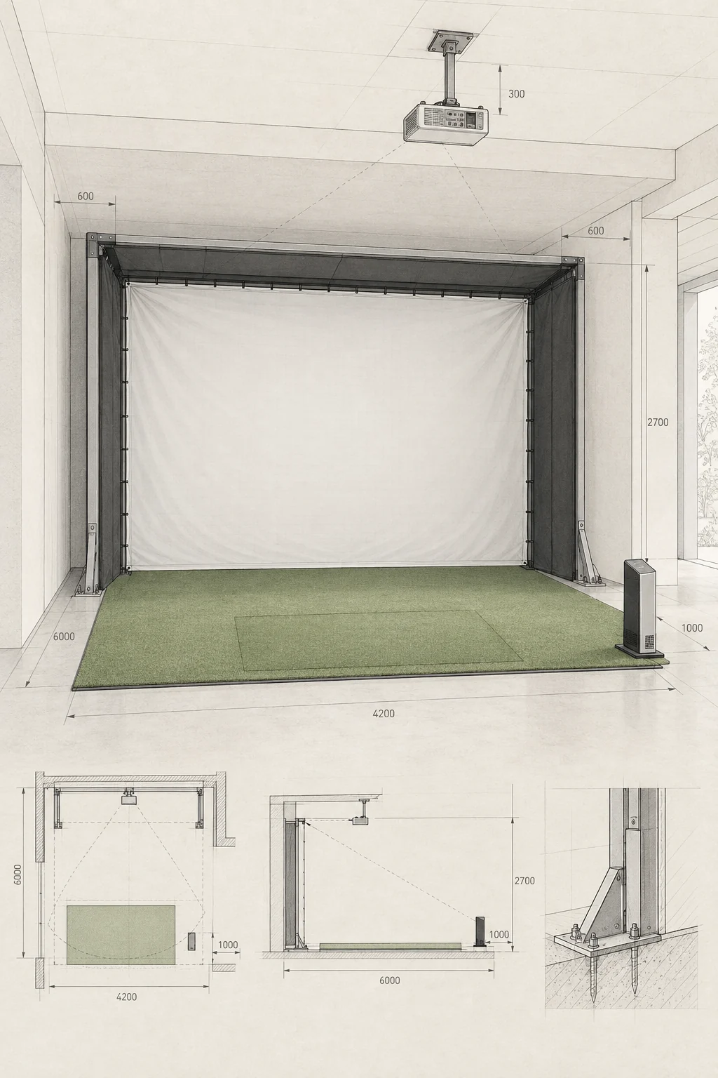
- Lens shift and image offset affect vertical placement and may constrain ceiling or wall positions.
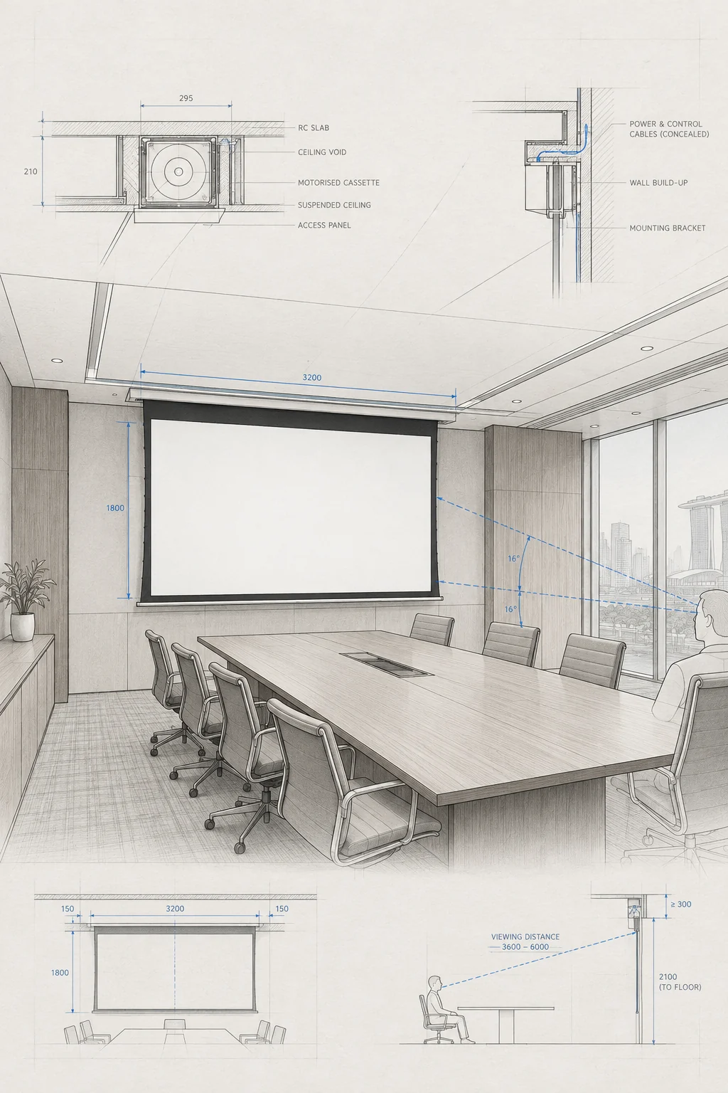
- The screen casing, frame, ceiling, beams, lights and service access may leave less usable distance than the room length suggests.
- Digital keystone or corner correction can change the image geometry and may reduce image quality; use the actual installation guidance for the model.
A conservative room check
- Confirm the exact projector model and lens/throw-ratio documentation.
- Measure visible image width and target aspect ratio.
- Mark the screen plane, casing/frame and projector lens position—not only the wall and ceiling points.
- Check throw distance at the minimum and maximum ratio if a zoom range is listed.
- Check image offset, lens shift, ceiling height, bracket depth and service access.
- Confirm signal, power, mounting structure and the worst-case viewing position.
- Test focus and alignment after installation and record the verified setting.
Next action
Share the calculator inputs with the projector model, screen width, room plan and mounting photos. The project team can then verify the lens range and the actual lens-to-screen position before a specification is issued.
Keep planning.
Start with a photo-first projector survey
Send a photo of the screen wall and projector position with the exact model, lens range, screen width and room plan.
Start with a photo-first projector survey